Robotics portfolioHexapod · 3D simulation · Robot joint · RC plane
Rhett Brewer
I’m 16, and I design, build, and program robots.

- Drawn by
- R. Brewer
- Subject
- Robots I design, build, and program
- Sheets
- 8
About
Rhett Brewer
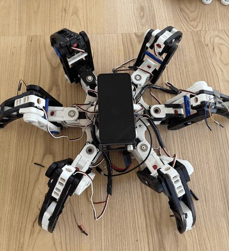
I’m a 16-year-old student and robotics engineer at Alpha School in Austin, Texas. I build robots from start to finish: I design them in CAD, build them, wire the electronics, program them and train them with reinforcement learning.
28 s · loops
What’s on it
1Android phone
The brain. It runs my app and sends every servo command, and I use its gyro for self-balancing. There’s no Raspberry Pi.
2Servo
One per joint, three per leg. The femur servos carry the most load, so they are 35 kg; the rest are 25 kg.
3Battery
An 11.4 V LiPo that powers the whole robot.
4Buck converter
Steps the battery’s voltage down to what the electronics need.
| Servos | 18 | 12 × 25 kg, 6 × 35 kg |
|---|---|---|
| Servo controller | Pololu Maestro | 24 channels |
| Cost | under $500 | Whole robot; my target was $500 |
| Time to build | about a year | Mostly 3D printed, from an Aecert Robotics design I modified |
- Drawing
- HX-100
- Subject
- Hexapod
- Status
- Walking
Build log
-
On the desk. First legs
The first few legs moving.
-
On a tether cable. First steps
First steps! It was still wired, and the walking gaits weren’t perfect yet.
-
On a patio. Remote control
I added remote control, fixed the inverse kinematics and added smoothing, so it starts with small steps and gradually increases its speed and step length.
-
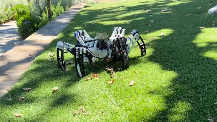
The video is at the top of this chapter. Self-balancing
The latest version. I added self-balancing with full-body rotation.
How it walks
I wrote the code that makes it walk. It picks a spot for each foot, and inverse kinematics works out the angles for that leg’s three servos.
Five gaits run on top of it:
- Tripod
- Ripple
- Wave
- Triple
- Spidercustom, spider-style
Chapter 2: 3D simulation
My own robot training app, built on MuJoCo.
My simulator maps a building with SLAM, no GPS: the robot draws the map and works out where it is on it at the same time. The map on the left fills in as the robot explores the building on the right.
- Drawing
- SM-200
- Subject
- 3D simulation
- Status
- Beta
Mapping a building
Training your robot
You upload a robot’s CAD model, and four steps later you get a trained policy. A policy is the learned controller that decides how the robot moves.
Its look is Blender-inspired. Underneath it’s MuJoCo, a Python backend and a React and three.js front end.
Learning from cameras
I want a simulated arm to do each task using only its cameras, because a real robot has to find objects with its cameras too.
| Task | Target | Result | Trials |
|---|---|---|---|
| Pick and place Camera student | 70% | 100% | ~25 |
| Push Camera student | 70% | 81% | ~25 |
| Sort by color Teacher | — | 95.8% | [TRIALS] |
- Tasks it trains on
- Reach
- Pick and place (result in the table)
- Push (result in the table)
- Stack
- Sort by color (result in the table)
- Open a drawer
- Randomized in training
- Object size
- Color
- Position
- Lighting
- Camera noise
Tasks in yellow have a result in the table. Reach, stack and the drawer don’t have results yet.
The simulator knows exactly where every object is. So I give those positions to a teacher policy, and it learns a task fast. Its successful attempts become training examples for a student policy that only gets the wrist and overhead camera images, the kind of view a real robot would have.
Training a two-armed robot
Chapter 3: Robot joint
The shoulder of a cable-driven 6-axis arm I designed for accuracy. Only the shoulder is built so far.
The goal is an arm that goes back to the same spot within 0.5 mm, every time. The budget is about $2,500, mostly printed parts.
- Drawing
- RJ-300
- Subject
- Shoulder joint
- Rev
- C
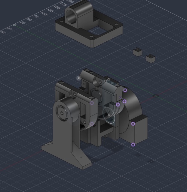
How the joint is geared
The Mini CIM motor spins fast but with little torque. Three stages slow it down and turn that speed into torque, and each kind of reducer has its own upsides and downsides. A 4:1 belt comes first because belts are fine at high speed, and it moves the turning axis away from the motor. Next is a 16:1 planetary gearbox, a big reduction in a small space. Last is an 8:1 capstan, a rope drive with almost no backlash (the little bit of play between parts).
- A Mini CIM: fast, low torque
- B Belt 4:1: good at high speed, moves the axis away from the motor
- C Planetary 16:1: a big reduction in a small space
- D Dyneema capstan 8:1: 135 mm sector, 2 mm rope, almost no backlash. The output. The motion goes through a rope, not gears. The rope is pulled tight both ways and never goes slack, so when the drum turns back, the sector turns back right away. It’s Dyneema DM20, which has almost no creep (it doesn’t slowly stretch under load).
Joint testing
Repeatability is how close the arm gets back to the same spot every time it returns. My target is 0.5 mm; the shoulder measured ±0.22 mm.
| Test | Result |
|---|---|
| Repeatability | ±0.22 mm PassTarget 0.5 mm. Dial indicator, 20 trials. See the test on Reddit. |
| Shoulder lift | 10 lb at 16 in5 lb at 8 in |
| Cost to build | Under $200 |
Chapter 4: RC plane
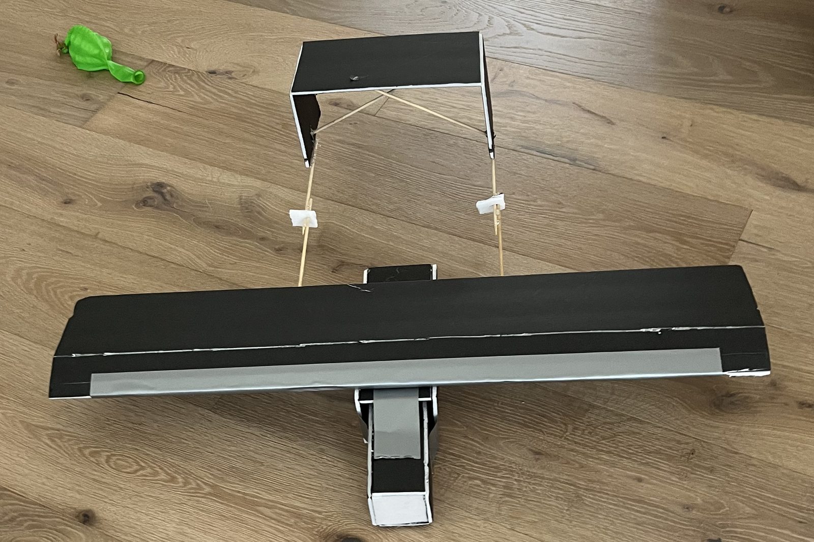
One of my very first projects. I built it in 7th grade, and it's what got me to keep building. It flew in October 2023.
- Built
- 7th grade
- Subject
- RC airplane
- Flown
- Oct 2023
9 s · loops
Skills
- Mechanical
- What I can do: I can design and model parts in CAD, from single parts to whole robots.
- Where I learned itHexapod, page Robot joint, page
More: Mechanical
I 3D print most of what I design. My hexapod’s frame is mostly printed parts.
- Electronics
- What I can do: I can do the electronics for my robots: wiring, motor drivers, sensors and power.
- Where I learned itRobot joint, page
More: Electronics
The robot joint runs on an ESP32 with a BTS7960 motor driver, an AS5600 encoder on the joint and an ACS758 current sensor for its torque limit.
- Controls
- What I can do: I can write inverse kinematics code, gyro-adaptive balance, and the control software that runs my robots.
- Where I learned itHexapod, page Robot joint, page
More: Controls
I wrote the robot joint’s closed-loop position control and current limit, and my hexapod’s five gaits.
- Robot learning
- What I can do: I can train robots with reinforcement learning in my own MuJoCo simulator, and train camera-based policies for harder tasks in changing environments.
- Where I learned it3D simulation, page
More: Robot learning
In my simulator, an arm that knows where everything is learns a task first. Its successful attempts then train an arm that only uses cameras.
- Perception
- What I can do: I can give robots simulated cameras, depth and lidar in my simulator, and map a building with SLAM.
- Where I learned it3D simulation, page
More: Perception
The camera arms work from a wrist camera and an overhead camera.
- Software
- What I can do: I can write the software around my robots: Python backends, React and three.js front ends, and Android apps.
- Where I learned itHexapod, page 3D simulation, page
More: Software
Python runs my simulator’s backend and React and three.js its front end. My web sim of the hexapod is three.js, and my own Android app runs the real one.
End of the book
Contact
- Name
- Rhett Brewer
- brhett195@gmail.com